Pressure Reducing
Control Valve
F115 (Globe) F1115 (Angle)
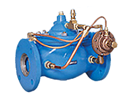
The Watts ACV Pressure Reducing Control Valve is designed to automatically reduce a fluctuating higher upstream pressure to a constant lower downstream pressure regardless of varying flow rates. It is controlled by a normally open, pressure reducing pilot designed to: 1) Open (allowing fluid out of the main valve cover chamber) when downstream pressure is below the adjustable setpoint, and 2) Close (allowing fluid to fill the main valve cover chamber) when downstream pressure is above the adjustable setpoint. A decrease in downstream pressure causes the valve to modulate toward an open position, raising downstream pressure. An increase in downstream pressure causes the valve to modulate toward a closed position, lowering downstream pressure.
The Pressure Reducing Control Valve shall be a pilot operated diaphragm valve designed to automatically reduce a fluctuating higher upstream pressure to a constant lower downstream pressure regardless of varying flow rates.
The main valve shall be a hydraulically operated, single diaphragm actuated, globe or angle pattern valve. Y-pattern valves shall not be permitted. The valve shall contain a disc and diaphragm assembly that forms a sealed chamber below the valve cover, separating operating pressure from line pressure. The diaphragm shall be constructed of nylon reinforced Buna-N, and shall not seal directly against the valve seat and shall be fully supported by the valve body and cover. Rolling diaphragm construction will not be allowed and there shall be no pistons operating the main valve or any pilot controls.
The main valve body and cover shall be Ductile Iron ASTM A536, and all internal cast components shall be Ductile Iron or CF8M (316) Stainless Steel. All Ductile Iron components, including the body and cover, shall be lined and coated with an NSF 61 Certified Epoxy Coating applied by the electrostatic heat fusion process. All main valve throttling components (valve seat and disc guide) shall be Stainless Steel. The valve body and cover must be machined with a 360-degree locating lip to assure proper alignment.
The disc and diaphragm assembly shall contain a Buna-N synthetic rubber “Quad Seal” that is securely retained on 3-1/2 sides by a disc retainer and disc guide. Diaphragm assemblies utilizing bolts or cap screws for component retention will not be permitted. The exposed portion of the Quad Seal shall contact the valve seat and seal drip-tight. The disc and diaphragm assembly must be guided by two separate bearings, one installed in the valve cover and one concentrically located within the valve seat, to avoid deflection and assure positive disc-to-seat contact. Center guided valves will not be permitted. All necessary repairs shall be made from the top of the valve while the body remains in line.
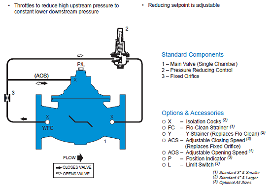
Pilot control systems for valves 3” and smaller shall contain a Flow Clean Strainer, Fixed Orifice Closing Speed, Adjustable Opening Speed Control and Pressure Reducing Pilot. Pilot control systems for valves 4” and larger shall contain an external Y-Strainer, Fixed Orifice Closing Speed, Pressure Reducing Pilot and Isolation Ball Valves on all body connections. All pilot control systems shall utilize copper tubing and brass fittings regardless of valve size. The adjustment range of the pressure reducing pilot shall be 30-300 psi.
The valve shall be Watts ACV Model F115 or (Globe) or F1115 (Angle) pattern Pressure Reducing Control Valve.
Schematics:
Materials:
Body & Cover:	 Ductile Iron ASTM A536

Coating:			 NSF Listed Fusion
				 Bonded Epoxy Lined
				 and Coated

Trim:			 316 Stainless Steel (1-1/4” – 8”)
				 ASTM B62 Bronze (10”)
				 (Stainless Steel Optional)

Elastomers:		 Buna-N (standard)
				 EPDM (optional)
				 Viton (optional)

Stem, Nut & 		 Stainless Steel
Spring:
Operating Pressure:
Threaded = 400 psi
150 Flanged = 250 psi
300 Flanged = 400 psi
Operating Temperature:
Buna-N: 160°F Maximum
EPDM: 300°F Maximum
Viton: 250°F Maximum
Pilot System:
Reducing Control
20-175 psi (Standard)
0-30 psi (Optional)
100-300 psi (Optional)
Tubing & Fittings:
Copper / Brass (Standard)
Stainless Steel (Optional)
Dimensions — Weights:
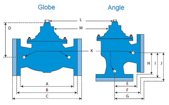
| VALVE SIZE | A | B | C | D | E | F | G | H | I | J | K | L | M | SHIPPING WEIGHTS* |
|---|---|---|---|---|---|---|---|---|---|---|---|---|---|---|
| GLOBE THRD. | GLOBE 150# | GLOBE 300# | COVER TO CENTER | ANGLE THRD. | ANGLE 150# | ANGLE 300# | ANGLE THRD. | ANGLE 150# | ANGLE 300# | PORT SIZE | PORT SIZE | PORT SIZE | ||
| 1-1/4 | 7-1/4 | - | - | 3-1/2 | 3-1/4 | - | - | 1-7/8 | - | - | 1/4 | 1/2 | 1/8 | 15 |
| 1-1/2 | 7-1/4 | 8-1/2 | 9 | 3-1/2 | 3-1/4 | 4 | - | 1-7/8 | 4 | - | 1/4 | 1/2 | 1/8 | 15 |
| 2 | 9-3/8 | 9-3/8 | 10 | 4-15/16 | 4 | 4 | 4-1/4 | 4 | 4 | 4-1/4 | 1/2 | 1/2 | 1/4 | 35 |
| 2-1/2 | 11 | 11 | 11-5/8 | 7 | 5-1/2 | 5-1/2 | 5-13/16 | 4 | 4 | 4-5/16 | 1/2 | 1/2 | 3/8 | 65 |
| 3 | 10-1/2 | 12 | 13-1/4 | 7 | 5-1/4 | 5-3/4 | 6-1/8 | 5-1/4 | 5-3/4 | 6-1/8 | 1/2 | 1/2 | 3/8 | 95 |
| 4 | - | 15 | 15-5/8 | 8-5/8 | - | 6-3/4 | 7-1/8 | - | 6-3/4 | 7-1/8 | 1/2 | 1/2 | 3/8 | 190 |
| 6 | - | 20 | 21 | 11-3/4 | - | 8-1/2 | 8-7/8 | - | 8-1/2 | 8-7/8 | 1/2 | 1/2 | 1/2 | 320 |
| 8 | - | 25-3/8 | 26-3/8 | 15-3/4 | - | 11 | 11-1/2 | - | 11 | 11-1/2 | 1/2 | 1 | 1/2 | 650 |
| 10 | - | 29-3/4 | 31-1/8 | 18-3/4 | - | 14-7/8 | 15-5/8 | - | 14-7/8 | 15-5/8 | 1 | 1 | 1 | 940 |
* For larger sizes consult factory
Valve Cover Chamber Capacity:
| Valve Size (in) | 1-1/4 | 1-1/2 | 2 | 2-1/2 | 3 | 4 | 6 | 8 | 10 |
|---|---|---|---|---|---|---|---|---|---|
| fl.oz. | 4 | 4 | 4 | 10 | 10 | 22 | 70 | - | - |
| U.S. Gal | - | - | - | - | - | - | - | 1-1/4 | 2-1/2 |
Valve Travel:
| Valve Size (in) | 1-1/4 | 1-1/2 | 2 | 2-1/2 | 3 | 4 | 6 | 8 | 10 |
|---|---|---|---|---|---|---|---|---|---|
| Travel (in) | 3/8 | 3/8 | 1/2 | 5/8 | 3/4 | 1 | 1-1/2 | 2 | 2-1/2 |
Sizing:
| Size (in) | 1-1/4 | 1-1/2 | 2 | 2-1/2 | 3 | 4 | 6 | 8 | 10 |
|---|---|---|---|---|---|---|---|---|---|
| Maximum Continuous (GPM) | 95 | 130 | 210 | 300 | 485 | 800 | 1850 | 3100 | 5000 |
| Maximum Intermittent (GPM) | 119 | 161 | 265 | 390 | 590 | 1000 | 2300 | 4000 | 6250 |
| Minimum Continuous (GPM) | 1 | 1 | 1 | 20 | 30 | 50 | 115 | 200 | 300 |
Maximum continuous flow based on velocity of 20 ft. per second.
Maximum intermittent flow based on velocity of 25 ft. per second.
Minimum continuous flow based on velocity of 1 ft. per second.
NOTE: The above chart is a suggested guide. Inlet pressure, outlet pressure, minumum, normal and maximum flow rates should be considered for specific valve sizing. Contact Watts ACV for details.
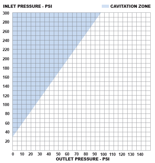
Cavitation Chart:
After selecting the valve size, locate inlet and outlet pressures on this chart. If the intersection point falls in the shaded area, cavitation can occur. Operation of valves continually in the cavitation zone should beavoided. Consult Watts ACV for alternatives.
Series PL

The Series PL™ close coupled booster pumps are specifically designed for quiet operation in hydronic, radiant and geothermal heating and cooling systems.
Más...
Oil Lubricated Circulators Three-Piece

B&G Motor — The heart of the Booster. The finest circulator motor available. Sleeve bearing, oil lubricated with replaceable resilient motor mounts.
Más...
Series 60 In-Line Mounted Centrifugal Pump

Maintenance-Free Pump and Motor Design. Bell & Gossett’s time-proven three-piece design provides you with worry-free, install-and-forget operation and reliability.
Más...

IDEMSA
Unión 27, Local P. B.
Col. Escandón
C. P. 11800, México, D. F.
Email: bygidemsa@prodigy.net.mx
Tel.: (55) 5272-0219
Fax: (55) 5516-1698