Series 25AUB-Z3
Water Pressure Reducing Valves*
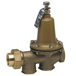
Series 25AUB-Z3 Water Pressure Reducing Valves are designed to reduce incoming water pressure to a sensible level to protect plumbing system components and reduce water consumption.
This series is suitable for water supply pressures up to 300psi (20.7 bar) and may be adjusted from 25 – 75psi (172 – 517 kPa).
The standard setting is 50psi (345 kPa).
All parts are quickly and easily serviceable without removing the valve from the line.
The standard bypass feature permits the flow of water back through the valve into the main when pressures, due to thermal expansion on the outlet side of the valve, exceed the pressure in the main supply.
Features:
Standard construction includes Z3 sealed spring cage and stainless steel corrosion resistant
adjusting & cage screws for accessible outdoor or pit installations.

Union inlet connection.

Integral stainless steel strainer.

Replaceable seat module.

Bronze body construction.

Serviceable in line.

Bypass feature controls thermal expansion pressure**

High temperature resistant reinforced diaphragm for hot water
Models:
25AUB-Z3						 NPT threaded female union inlet x NPT female outlet

25AUB-S-Z3						 Solder union inlet x NPT female outlet

25AUB-DU-Z3					 Double Union – NPT threaded union female inlet and outlet

25AUB-S-DU-Z3					 Double Union – Solder union inlet and outlet

25AUB-DU-THDxPEX-Z3			 Double Union – NPT threaded female inlet and PEX union outlet

25AUB-DU-LF-Z3					 Double union body less fittings (3⁄4", 1", 11⁄4")

25AUB-QC-Z3					 Single Union – Quick-Connect union inlet (1⁄2", 3⁄4", 1")

25AUB-QC-Z3					 Single Union – Quick-Connect union inlet (1⁄2", 3⁄4", 1")

25AUB-DU-QC-Z3				 Double Union – Quick-Connect inlet and outlet (1⁄2", 3⁄4", 1")
Sizes:
1/2" – 2" (15 – 50mm)
Specifications:
Standard Specifications: A Water Pressure Reducing Valve with intergral strainer shall be installed in the water service pipe near its entrance to the building where supply main pressure exceeds 60psi (413 kPa) to reduce it to 50psi (345 kPa) or lower.
The valve shall feature a bronze body suitable for water supply pressures up to 300psi (20.7 bar). Provision shall be made to permit the bypass flow of water back through the valve into the main when pressures, due to thermal expansion on the outlet side of the valve, exceed the pressure in the main supply. Water Pressure Reducing Valve with built-in bypass check valves will be acceptable.
Approved valve shall be listed to ASSE 1003 and IAPMO and certified to CSA B356. Valve shall be a Watts Series 25AUB-Z3.*
*A water saving test program concluded that reducing the supply pressure from 80-50psi (551-345 kPa) resulted in a water savings of 30%.
** The bypass feature will not prevent the pressure relief valve from opening on the hot water supply system with pressure above 150psi (10.3 bar).
Materials:
Body:					 Bronze

Seat:					 1⁄2"–1" (15–25mm) Replaceable engineered polymer (10% glass filled Noryl®)

						 11⁄4"–2" (32–50mm) Replaceable stainless steel

Integral Strainer:			 Stainless steel

Diaphragm:				 Reinforced EPDM

Valve Disc:				 EPDM
Note: for LP models where application temperatures exceed 160°F (71°C), but not over 180°F (82°C), a Teflon® protector should be added to sizes 11⁄4"–2" (32-50mm).
Pressure – Temperature:
Temperature Range:						 33°F – 160°F (0.5°C – 71°C)

Maximum Working Pressure:				 300psi (20.7 bar)

Adjustable Reduced Pressure Range:		 25–75psi (172 – 517 kPa)

Standard Reduced Pressure Setting:		 50psi (345 kPa)
Options:
Add Suffix
G		Gauge tapping, 1/4" (8mm) on 1/2" & 3⁄/4", all other sizes 1/8" (3mm)
GG		Gauge tapping and 160psi (11 bar) gauge
HP		High pressure range 75–125psi (5.2 – 8.6 bar)
LP		Low pressure range 10–35psi (69 – 241 kPa)
Z7		400psi (27.6 bar) initial pressure, 1/2" (20mm) models only

Noryl® is a registered trademark of SABIC Innovative Plastics™.
Teflon® is a registered trademark of E.I. Dupont de Nemours & Company.
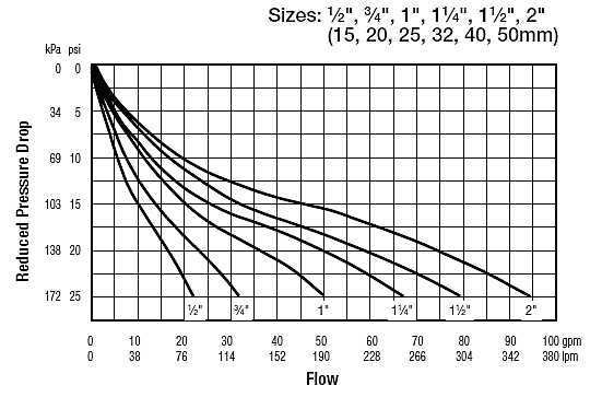
Capacity:
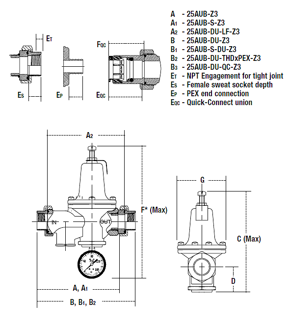
Dimensions — Weights:
| SIZE (DN) | DIMENSIONS | ||||||||||||||
|---|---|---|---|---|---|---|---|---|---|---|---|---|---|---|---|
| A | A1 | A2 | B | B1 | B2 | C | |||||||||
| in. | mm | in. | mm | in. | mm | in. | mm | in. | mm | in. | mm | in. | mm | in. | mm |
| 1⁄2 | 15 | 53⁄8 | 137 | 55⁄16 | 135 | 53⁄16 | 132 | 67⁄16 | 164 | 63⁄8 | 162 | – | – | 7 | 178 |
| 3⁄4 | 20 | 55⁄16 | 135 | 51⁄2 | 140 | 51⁄4 | 133 | 61⁄2 | 165 | 67⁄8 | 175 | 63⁄4 | 171 | 7 | 178 |
| 1 | 25 | 6 | 152 | 61⁄4 | 159 | 57⁄8 | 149 | 73⁄8 | 187 | 713⁄16 | 198 | 711⁄16 | 195 | 8 | 203 |
| 11⁄4 | 32 | 83⁄4 | 222 | 815⁄16 | 227 | 81⁄4 | 210 | 103⁄4 | 273 | 11 | 279 | – | – | 9 | 229 |
| 11⁄2 | 40 | 83⁄4 | 222 | 9 | 229 | 81⁄4 | 210 | 103⁄4 | 273 | 113⁄16 | 284 | – | – | 91⁄2 | 241 |
| 2 | 50 | 91⁄4 | 235 | 10 | 254 | 83⁄4 | 222 | 115⁄16 | 287 | 1211⁄16 | 322 | – | – | 111⁄4 | 286 |
| DIMENSIONS | WEIGHT | ||||||||||||||||
|---|---|---|---|---|---|---|---|---|---|---|---|---|---|---|---|---|---|
| D | F * | G | ET | ES | EP | EQC | FQC | ||||||||||
| in. | mm | in. | mm | in. | mm | in. | mm | in. | mm | in. | mm | in. | mm | in. | mm | lbs. | kgs. |
| 11⁄2 | 38 | 97⁄16 | 240 | 31⁄8 | 79 | 1⁄2 | 13 | 1⁄2 | 13 | – | – | 17⁄8 | 36 | 11⁄2 | 38 | 3.5 | 1.6 |
| 11⁄2 | 38 | 97⁄16 | 240 | 31⁄8 | 79 | 1⁄2 | 13 | 3⁄4 | 19 | 5⁄8 | 16 | 19⁄16 | 40 | 111⁄16 | 42 | 3.5 | 1.6 |
| 13⁄4 | 44 | 107⁄16 | 266 | 35⁄8 | 92 | 5⁄8 | 16 | 15⁄16 | 23 | 13⁄16 | 21 | 111⁄16 | 43 | 13⁄4 | 45 | 6.5 | 3 |
| 21⁄8 | 54 | 117⁄16 | 291 | 35⁄8 | 92 | 5⁄8 | 16 | 1 | 25 | – | – | – | – | – | – | 10 | 4.5 |
| 23⁄8 | 60 | 1115⁄16 | 304 | 41⁄16 | 103 | 5⁄8 | 16 | 11⁄16 | 28 | – | – | – | – | – | – | 10 | 4.5 |
| 31⁄4 | 83 | 1311⁄16 | 348 | 43⁄4 | 121 | 5⁄8 | 16 | 15⁄16 | 34 | – | – | – | – | – | – | 15 | 6.8 |
Series PL

The Series PL™ close coupled booster pumps are specifically designed for quiet operation in hydronic, radiant and geothermal heating and cooling systems.
Más...
Oil Lubricated Circulators Three-Piece

B&G Motor — The heart of the Booster. The finest circulator motor available. Sleeve bearing, oil lubricated with replaceable resilient motor mounts.
Más...
Series 60 In-Line Mounted Centrifugal Pump

Maintenance-Free Pump and Motor Design. Bell & Gossett’s time-proven three-piece design provides you with worry-free, install-and-forget operation and reliability.
Más...

IDEMSA
Unión 27, Local P. B.
Col. Escandón
C. P. 11800, México, D. F.
Email: bygidemsa@prodigy.net.mx
Tel.: (55) 5272-0219
Fax: (55) 5516-1698